4 Pin Mini Xlr Wiring Diagram - Custom Usb Cables Pinout With 4 Pin Mini Xlr By Kriscables Kriscables / #plug to xlr dmx cable.
4 Pin Mini Xlr Wiring Diagram - Custom Usb Cables Pinout With 4 Pin Mini Xlr By Kriscables Kriscables / #plug to xlr dmx cable.. Mx 3 pin 4 pin 5 pin mini xlr type connector is a type of connector used for many professional audio applications. Xlr pin 2 to 1/4 plug tip. Xlr to inch stereo jack plug. Pin 1 is shorted to pin 3, at either end of the cable how to wire a 1/4 jack plug (unblanced) the tip of the jack is 'hot' and carries the positive going signal, whilst the sleeve is 'cold' and carries the ground. 3 pin xlr wiring standard.
Bridging 1&4 for signal, 2&3 for ground) 2. 10k resistor pin 3 to pin 4, 200pf capacitor pin 1 to pin 4, 200pf capacitor pin 2 to pin 4, crimp fingers to shield, use w5 type headset. 5 pin & 3 pin xlr wiring pinout information. Wiring also compatible with tv logic monitors and alphatron evf. According to 4 reports in our database ( 4 positive and 0 negative) the 4 pin xlr connector pinout should be correct.
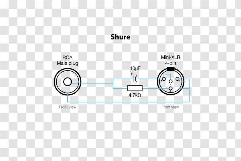
Microphone Shure Sm58 Xlr Connector Wiring Diagram Pinout Transparent Png from img1.pnghut.com The following xlr 4 pin wiring diagram photo have been authored. 3 pin xlr wiring standard. 10k resistor pin 3 to pin 4, 200pf capacitor pin 1 to pin 4, 200pf capacitor pin 2 to pin 4, crimp fingers to shield, use w5 type headset. K712 and other k701 derivatives like the quincy jones q701. For a low level signal, note that a standard xlr. An explanation and diagram showing how to wire an xlr (cannon) connector to a 1/4 inch mono phone (jack) connector.the 1/4 connector, on the other hand, can have 2 or 3 wire terminals and is not standard. Mini 4pin xlr female to full 4pin xlr male. #plug to xlr dmx cable.
K712 and other k701 derivatives like the quincy jones q701.
A wiring diagram usually gives assistance nearly the relative perspective and treaty of devices and. Xlr to 1/4 trs connector (wired for balanced mono). Pin 2 on the xlr is 'hot' and carries the positive going signal, whilst pin 3 is 'cold' and provides the return. Shield & negative connect short together. Bridging 1&4 for signal, 2&3 for ground) 2. On the four pin amphenol, pin 2 is a high impedance, unbalanced output. Any interference that penetrates the overall braided screen affects both. #standard xlr wiring diagram yamaha. Talk to a sales representative. Pin 3 & pin 4: Xlr pin 2 = low impedance audio hot (amphenol pin 4, white wire, typically) xlr pin 3 = low impedance audio return (amphenol pin 3, black wire, typically) note: For 3 wires condenser microphone ( such as : An explanation and diagram showing how to wire an xlr (cannon) connector to a 1/4 inch stereo jack connector.
Cable length is 8 inches (20.3 cm). An explanation and diagram showing how to wire an xlr (cannon) connector to a 1/4 inch mono phone (jack) connector.the 1/4 connector, on the other hand, can have 2 or 3 wire terminals and is not standard. Heavy gauge wires can withstand more than 10a at 14.4v. Mx xlr adapters do not suffer from inse. Xlr pin 1 = shield, amphenol pin 1.
Leads Direct Xlr Connectors Wiring from www.leadsdirect.co.uk Pin 2 on the xlr is 'hot' and carries the positive going signal, whilst pin 3 is 'cold' and provides the return. Mx xlr adapters do not suffer from inse. Xlr pin 1 to 1/4 plug sleeve. Negative (for bias voltage) for dynamic microphone. Mx 3 pin 4 pin 5 pin mini xlr type connector is a type of connector used for many professional audio applications. Xlr to 1/4 inch mono wiring diagram. It shows the components of the circuit as simplified shapes, and the capacity and signal links together with the devices. Pin 2 on the xlr is 'hot' and carries the positive going signal, whilst pin 3 is 'cold' and provides the return.
Talk to a sales representative.
Pin 1 is shorted to pin 3, at either end of the cable how to wire a 1/4 jack plug (unblanced) the tip of the jack is 'hot' and carries the positive going signal, whilst the sleeve is 'cold' and carries the ground. Mx 3 pin 4 pin & 5 pin mini xlr type connector is a type of connector used for many professional audio applications. #standard xlr wiring diagram yamaha. Pin 1 & pin 2: 10k resistor pin 3 to pin 4, 200pf capacitor pin 1 to pin 4, 200pf capacitor pin 2 to pin 4, crimp fingers to shield, use w5 type headset. Talk to a sales representative. Xlr pin 3 to 1/4 plug ring. A wiring diagram usually gives assistance nearly the relative perspective and treaty of devices and. Wiring also compatible with tv logic monitors and alphatron evf. Aug 05, · the absolute correct, proper wiring for a transmitter mini plug fed from a fp33 at mic level, balanced! The above diagram shows you the pin numbering for both male and female xlr connectors, from the front and the rear view. This wiring configuration gives you a balanced mono audio cable. Negative (for bias voltage) for dynamic microphone.
Xlr pin 2 = low impedance audio hot (amphenol pin 4, white wire, typically) xlr pin 3 = low impedance audio return (amphenol pin 3, black wire, typically) note: Any interference that penetrates the overall braided screen affects both. 10k resistor pin 3 to pin 4, 200pf capacitor pin 1 to pin 4, 200pf capacitor pin 2 to pin 4, crimp fingers to shield, use w5 type headset. Pin 2 on the xlr is 'hot' and carries the positive going signal, whilst pin 3 is 'cold' and provides the return. Aug 05, · the absolute correct, proper wiring for a transmitter mini plug fed from a fp33 at mic level, balanced!
Akg C519ml Mic With Xd V75 And Tbp12 Beltpack Xd V Digital Wireless Microphones Line 6 Community from line6.com Xlr pin 2 to 1/4 plug tip. Pin 3 & pin 4: This wiring configuration gives you a balanced mono audio cable. Xlr to 1/4 inch mono wiring diagram. Xlr pin 2 to 1/4 plug tip. Xlr pinout (balanced) a balanced system is used in pro audio systems (xlr wiring diagram shown below), with an overall screen covering a twisted pair. Pin 2 on the xlr is 'hot' and carries the positive going signal, whilst pin 3 is 'cold' and provides the return. #standard xlr wiring diagram yamaha.
Xlr pinout (balanced) a balanced system is used in pro audio systems (xlr wiring diagram shown below), with an overall screen covering a twisted pair.
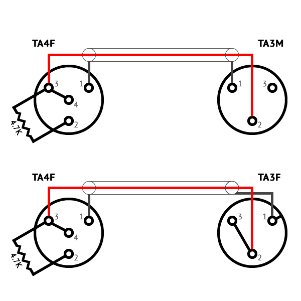
Heavy gauge wires can withstand more than 10a at 14.4v. On the four pin amphenol, pin 2 is a high impedance, unbalanced output. #plug to xlr dmx cable. Xlr pin 1 = shield, amphenol pin 1. Xlr pin 2 to 1/4 plug tip. The adapter cable on top is for connecting to an amplifier's speaker out terminals. 3 pin xlr wiring standard. The following xlr 4 pin wiring diagram photo have been authored. This wiring configuration gives you a balanced mono audio cable. (the rear view is the end you solder from) here are the connections on each pin: #standard xlr wiring diagram yamaha. Shield & negative connect short together. The pictorial shows the pin layout of a ta4f connector, as viewed from the wiring side.
Adapts mini 4pin xlr (female) to standard 4pin xlr (male) mini xlr wiring. 3 pin xlr wiring standard.

Comments
Post a Comment